
-
By Rikupetteri Salminen

- Published Nov 21, 2013 in Gear Garage
Sure, you can get a distortion pedal that comes close to the sound you hear in your head. Or for extra credit, you could construct your own light-saber and become a Jedi.
A brief history of distortion.
In the mid 50's, when electric guitars became popular, all amplifiers were designed for vocals, and they didn't really give the edge guitarists wanted. The only way to get distortion was to turn the volume to eleven and hope the tubes didn't melt (or the neighbors didn't call the cops).
Coming to the sixties, guitarists razored their speaker cones to make a fuzzy sound. Later, the first distortion effect boxes were made to simulate the sound of razored cones and overdriven amps. These days most amps have built-in distortion, but distortion effects are still popular. Now we're going to discuss the methods of creating distortion with effect boxes.
The types of distortion.
When talking about distortion, you usually hear the words overdrive, distortion, fuzz and crunch. They are words describing the type of distortion an amp or an effect gives out. Overdrive is a natural and smooth sound, while a distortion is more rough. Fuzz is a metallic and very rough type of distortion that turns the sound of a guitar into a fuzzy sound. Crunch is not a specific type of distortion, but a mild overdrive or distortion. These don't apply to all effects on the market, for example Craig Anderton calls almost all of his distortions "fuzz", no matter if it's a distortion, overdrive or fuzz. For example Craig Anderton's Tube-sound Fuzz is actually an overdrive unit.
Roll your own.
The ultimate distortion comes from tubes that are overdriven so that they create a smooth singing sound. Nothing can mimic tubes, although there are a million different "tube-sound distortions" available. Usually distortion effects use solid state circuitry like transistors, op-amps and diodes, but there are a few commercial tube overdrive effects available like the Red Hot Chili's Tubester or PAiA Stack In a Box Kit.
The most common distortion types.
Overdriving transistors
Just like overdriving tubes, transistors are being overdriven by setting them to run at the top of the amplification range. This creates nasty, distorted tone.
Usually fuzzboxes use overdriven transistors. Check out different Fuzz Face-like designs to see what I mean. Different types of transistors distort differently. Silicon transistors make a nasty, metallic sound. Germaniums, which were used in the late sixties on the original Fuzz Face, have a little smoother sound. Unipolar transistors, such as jfets and mosfets have a softer, more tube-like tone.
"Hard" diode clipping
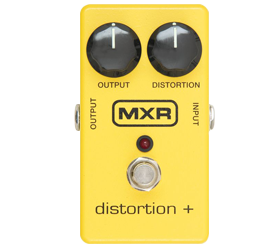
This is a very common way to create distortion. Two diodes shunt to ground the opposite way around will cut away the peaks of the signal and thus create distortion. Check out MXR Distortion+ to see what I mean (just click the purple icon).
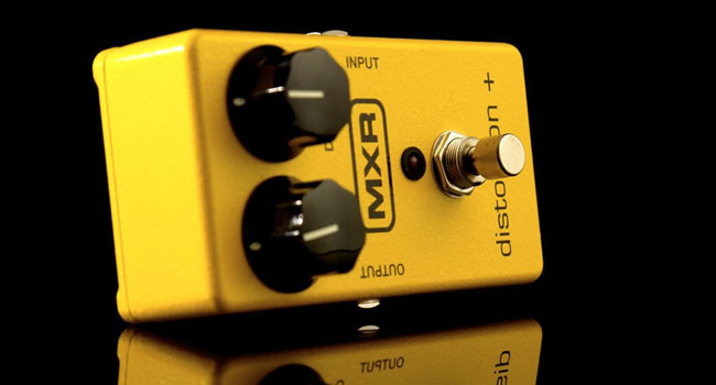
MXR Distortion+
MXR Distortion +
MXR Innovations came out with their MXR Distortion+ in the mid 1970s to critical acclaim. The picture of simplicity, this pedal sets itself apart with minimal circuitry and only two knobs. The control increases the amount of distortion while simultaneously cutting bass to improve clarity.
- Randy Rhoads

- Jerry Garcia

- Thom Yorke

For subtly different sounds try replacing D1 + D2 with 1n34's for fuzzy sounds, 1n4148 for more buzz, LEDs for more crunch or a 1n34 array like this:
The original diodes were germanium 1N270 types.
Effect could be improved with true bypass switching.
Components connected by dotted lines signify modifications for click prevention (1M resistor) and oscillation (cap in feedback loop).
"Soft" diode clipping
Another very common method, this creates a more overdrive-like sound than "hard" clipping distortions. Two diodes are connected on the feedback-path of an op-amp or a transistor. This rounds out the peaks of the signal and provides a tube-like tone. Ibanez Tube Screamer uses this method.
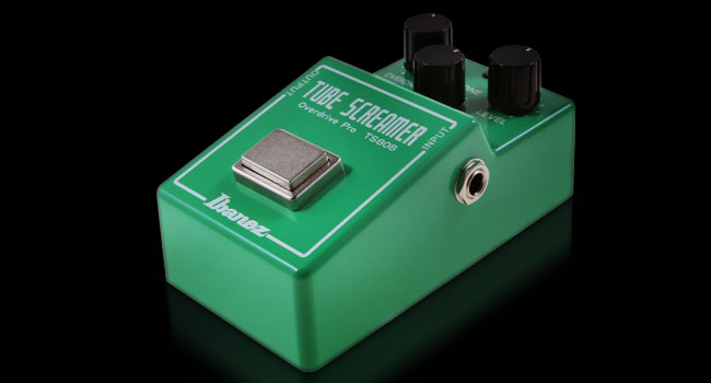
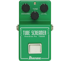
Ibanez Tube Screamer
Ibanez Tube Screamer
The Tube Screamer by Japanese guitar maker Ibanez has gone through many incarnations since its debut as the TS-808 in the 1970s. This distortion pedal is most popular with blues guitarists because of its mid-boosted tone, used to mimic the sound of a vintage tube amp.
- Stevie Ray Vaughan

- Noel Gallagher

- The Edge

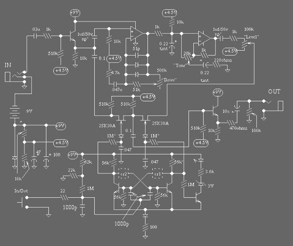
Op-amps are in dual 8 pin dip, 4558.
All transistors 2Sc1815.
All diodes silicon signal diodes, 1n914 or similar.
np* = non-polorized resistors denoted by * marked as 1M on original might be 22k and those marked 56K might 10k.
crf1 and cr2 are a special cap and resistor in parallel, the cap is 51p, the resistor is 56k.
Special methods
There are also different methods for creating distortion. To mention a few, there are zener diode clipping and CMOS inverters. Both are commonly used for tube-like tones. AMZ's Tube-like distortion uses zener diode clipping on the feedback path. CMOS inverters (CD4049's, usually) are used in designs such as MXR Hot Tubes distortion and Craig Anderton's Tube-sound fuzz.
A thing or two about Op-amps.
Op-amps (or operational amplifiers) are probably the most common component in creating distortion. To know a few op-amp basics won't hurt when designing distortion effects:
Op-amps can be configured to three different kind of stages:
- Inverting
- Non-Inverting
- Differential
The differential is very rare in distortion designs. It really doesn't have any advantages and is the most complicated, so we'll skip it.
A non-inverting preamp is a circuit where the input is connected to the non-inverting (+) input of the op-amp and a feedback loop is between the inverted input (-) and the output.
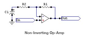
The gain of a non-inverting op-amp is set with resistors R1 and R2. The gain equals (R1 + R2)/R2. Values of a few kilo-ohms will be a good choice. A speciality of the non-inverting op-amp is C1. That capacitor along with R2 form a low-pass filter (explained later). A disadvantage of using non-inverting op-amps is that they can't have a gain less than 1, meaning that they can't attenuate the signal. But as this is useless in distortion effects, we can discard that.
An inverting preamp is a circuit where the input is connected to the inverting (-) input of the preamp through a resistor. Non-inverted (+) input is connected to ground.
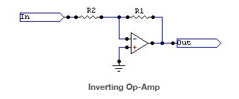
The gain of an inverting op-amp is set with resistors R1 and R2. The gain equals R1/R2. To avoid tone-loss, guitar amps and effects should have an input impedance of more than 100k ohms. And so, the input resistor R2 should be at least 100k. That means to have a gain of 10, R1 would have to be 1M or greater. Unfortunately, high resistor values mean high noise.
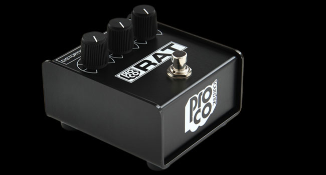
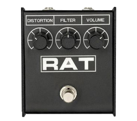
ProCo RAT
ProCo Rat
ProCo engineers Scott Burnham and Steve Kiraly designed The Rat while repairing Fuzz Face distortion pedals. They felt they could build a better mousetrap. Since then countless guitarists have relied on variations of the original. RAT's variable gain circuit distortion is similar to the classic Boss DS-1 distortion.
- Jeff Beck

- Kurt Cobain

- John Scofield

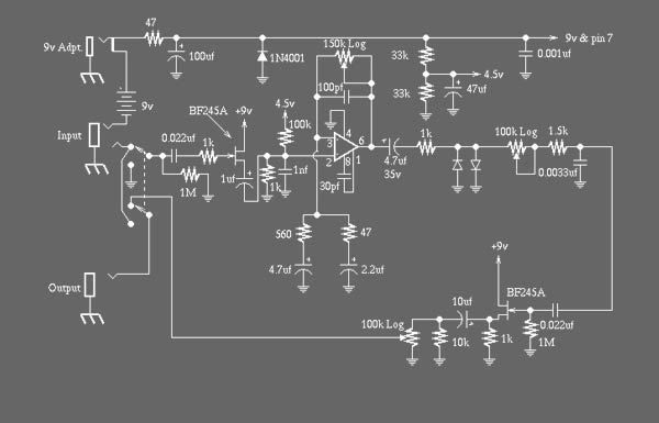
IC = LM308.
All diodes 1N4148.
Production of the RAT2 using a new PCB began in 1987, but the small box RAT continued to be produced. Many of these late issue small box black-face RATs were made with the new RAT2 PCB. These RATs often implement the RAT2 circuit minus the indicator LED bypass circuitry. They include R12 and R15 and have RAT2 values for R4 and possibly C13.
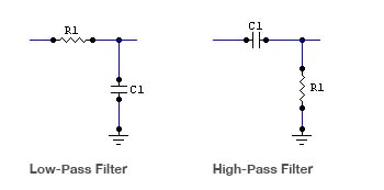
High- and low-pass filters.
To function properly, an effect has to have filters to reduce the frequencies being amplified. Filters will roll off the frequencies we don't. want to amplify. These are the high radio frequencies and the low noise frequencies. A simple (or first degree) filter is formed by a resistor and a capacitor shunt to ground. A high pass filter allows frequencies higher than the limit frequency to pass and lower frequencies are rolled off. A low pass filter is just the opposite.
Calculating the limit frequency is based on this formula:
f = 1/(2 * PI * R1 * C1)
Where f is frequency in hertz (Hz), R1 is value of R1 in ohms, and C1 is value of C1 in farads (F). If C1 is microfarads (µF), R1 must be mega-ohms.
Good limit frequency values could be 40Hz - 30,000Hz (30kHz). You might want to alter the low limit frequency, if your guitar is tuned down and using heavy-gauge strings (i.e., .013's) or designing the effect for bass guitar. You should not go under 20Hz because that's the lowest audible frequency.
Calculating the value of C1 works on the same formula like this:
C1 = 1/(2 * PI * R1 * f)
Example circuit:
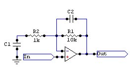
Gain = (10k + 1k)/1k = 11
The gain of a distortion unit is usually something from 100 - 200.
C1 = 1/(2 * PI * 0.001M * 40Hz) = 0,039µF = 39nF
39nF is not a standard value, so we'll have to use 50nF or 1µF. 22nF will have a limit frequency of 72Hz, which is too high for a downtuned guitar (low E is 82Hz). If I played bass, I'd go for the 1µF with 15Hz roll-off frequency, otherwise I'd take the 50nF with 31Hz roll-off frequency.
C2 = 1/(2 * PI * 0.01M * 30,000Hz) = 0,00053µF = 530pF
Again, 530pF is not a standard value, but 470pF will do. It gives a roll-off frequency of 33863Hz = 33kHz.
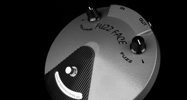
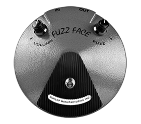
Dunlop Fuzz Face
Dunlop Fuzz Face
Arbiter Electronics introduced the Fuzz Face to the world in 1966. After achieving fame as Jimi Hendrix's go-to distortion pedal, the design was handed to a succession of companies ending with it's current owner, Dunlop, in 1993.
- Jimi Hendrix

- David Gilmour

- George Harrison

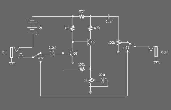
There are apparently two similar versions of the fuzz face. In one Q1 and Q2 were PNP germanium AC128 or NKT275 types. In the other, they were NPN silicon BC108C types.
Which type you choose to build will influence some of the other components. For a PNP version, the schematic is as shown. But if you build the NPN version, then the 470 ohm resistor marked by a * must be changed to 330 ohms and the battery and all the polarized capacitors must be reversed.
The original schematic is not exactly what is shown above. It had a very complex switching system which has been simplified (nothing has been lost, don't worry), and a unique grounding setup.
Aside from that, the schematic is exact with minor differences in components
on various units (eg. some had the 01uf cap listed as .047uf, which shouldn't make a difference as long as you feed a high impedance amp.
The transistors are hard to find. The thing to look for is germanium transistors with a decent gain factor (gain > 80). Note: silicon transistors will clip harshly and may not sound good, though 2n3905 has been said to work.
Types of power supplies.
Supplying power to op-amps isn't as simple as you could think. It isn't enough to connect a 9-volt battery to the V+ and V- pins on the op-amp, but an op-amp needs to be connected to a bipolar power supply or it needs to be biased to half of the input voltage.
Bipolar
Power supplies can be divided into two types: bipolar and unipolar. A normal battery—or a wall-wart—is a unipolar supply. Many AC transformer circuits use bipolar supplies. However batteries can be used to make bipolar supplies.
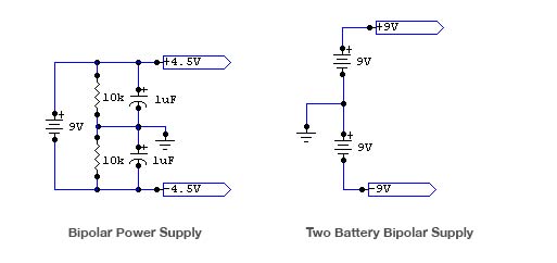
The two battery power supply is very rare with stompboxes, and the bipolar supply is also rarely used, but more common with small practice amp designs. Both of these can be used to power up your opamp if you don't want to use biasing (described later).
Biasing
Biasing is a common way to power up the op-amp while using unipolar supplies such as batteries or wall warts. Biasing is made by connecting two resistors from +9V to ground to half the voltage.
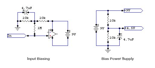
The above circuits are simple op-amp biasing circuits. They have two resistors connected from the battery + connector to ground and a capacitor to reduce hum. You can find this kind of biasing in almost every distortion effects. To mention a few, Ibanez Tube Screamer, MXR Distortion+ and ProCo Rat.
Choosing an op-amp.
There are so many op-amp types on the market that choosing the right one isn't that simple. However, experimenting with op-amps isn't that difficult.
Most op-amps use the same "standard" 741-pinout (which got has it's name from an old very common op-amp). Solder a socket on your PCB and you can easily change the op-amps. You could try bifet op-amps like the LF351 (low current drain) or LF356 (low noise) or with jfet opamps like TL071 (low noise) or TL081 (low current drain).
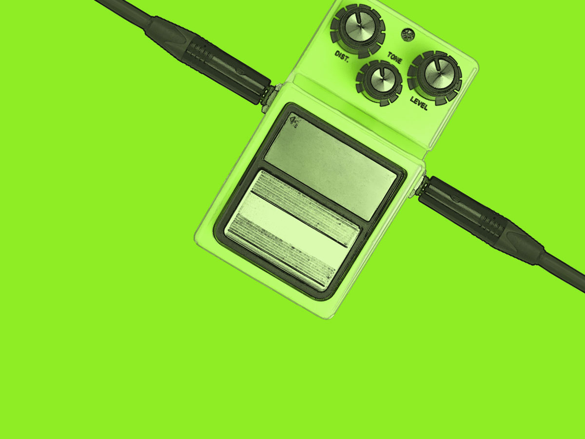
Knobs and controls.
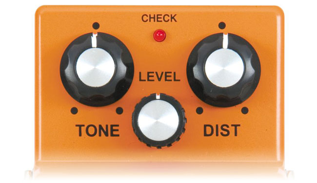
Distortion effects usually have three controls on them: Drive, Volume and Tone. The drive control adjusts the amount of distortion the effect puts out. Volume sets the amount of signal the effect puts out to the amp. And tone adjusts the color of the sound coming out of the effect. The tone control is usually an adjustable low-pass filter.
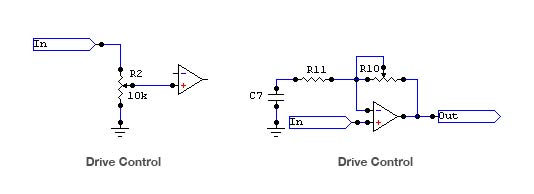
The above circuits use two different ways to control the amount of distortion. The first one is a volume control before the op-amp. This limits the amount of signal going into the circuit. The second one replaces the drive setting resistor of the op-amp. Turning the pot alters the gain of the op-amp. Note that this also changes the roll-off frequency of the high-pass filter around the op-amp.
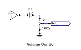
The above is a volume control circuit. This is almost the same on all distortion designs. The capacitor is protecting your amp from DC coming out of the op-amp. Note that this works as a tone control also, so I recommend using a capacitor value large enough that it doesn't affect the tone. 10µF should do it.
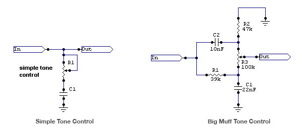
These two circuits represent different tone control circuits. The first one is a very common tone circuit. It is a variable low-pass filter. You can count a good capacitor value the same way we counted the low-pass filters earlier. A good pot value would be something from 100k to 500k.
The second one is a more complicated circuit, originally from a circuit called Big Muff. It has a low-pass (R1 and C1) and a high-pass (R2 and C2) filter and a linear pot (R3) that is used to control the filters. When you need just a little tone tweaking, use the simple tone control. If you need a versatile tone control that can sweep through the whole tone range, use the Big Muff.
Clipping diodes.
Choosing the clipping diodes of your distortion can be the most fun part of the designing process. Clipping diodes are like ice cream. Some like strawberry and some prefer chocolate.
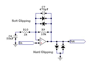
In the schematic above, you can see soft and hard clipping diodes. Soft and hard describe quite well the sound they produce. Soft clipping softly rounds out the signal peaks while hard clipping roughly cuts the signal peaks. See the oscilloscope view below to get an idea what I mean.
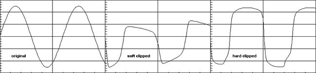
As you can see, the soft clipped wave is more softly rounded than the hard clipped one. The soft clipping was made with a Silicon/Germanium diode combination (1N4001 and 1N34) and the hard clipping was made with two silicon diodes (1N914's). There are many options for clipping diodes. You can try out 1N4001's (Si), 1N34's (Ge), 1N270's (Ge), 1N914's (Si) or LEDs.
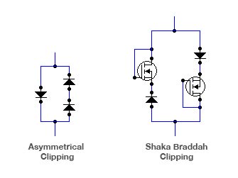
Above you can see special clipping diodes. The first has a single diode on one side and two on the other. This cuts down the positive or negative peaks (depending on how you connected the diodes) more than the other side.
The second one is from Jack A. Orman and Aaron Nelson's Shaka Braddah III design. It uses a diode and a MOSFET to create clipping. It gives a nice, bluesy soft clipping. The original diodes were 1N34's and the MOSFETs were IRF520's. When you've studied the basics of op-amps and diode clipping you can build your own designs.
Reprinted by permission of GeneralGuitarGadgets.com.
Rikupetteri Salminen, also known as Richardo X, knows his guitar effects. Check out more great DIY projects of his at www.generalguitargadgets.com/richardo/.