
-
By Mickey Delp

- Published Dec 3, 2013 in Gear Garage
There are those who buy and those who build. Mickey Delp is the latter. And this is how he set out to design a low cost drum machine.
This is the story of the design and development of the Delptronics LDB-1 Analog Drum Machine with a focus on the technical details.
I had been studying analog drum circuits for about a year, including both classic drum machines and more modern drum circuits and modules. In January of 2012, having just finished several projects, I felt it was time to dive into building some drum circuits.
A three month long beta test cycle really paid off.
My goal was to build a small, low cost drum machine, and I knew that the first step was to get the sounds right. I breadboarded every drum circuit I could find and compared the results with samples from classic drum machines, particularly the venerable Roland TR-808. I worked on it full time for two weeks. By the end of that time, I had the circuits refined, tuned and sounding just the way I wanted them.
I then went through the process of choosing a microcontroller to be the brains of the drum machine. That process is described in more detail below. I worked out the basic code for a microcontroller triggering the drums and built the prototype. Having worked out the bugs, I designed a printed circuit board and built several devices.
The most time-consuming step in the development of the LDB-1 was programing all of the features. I went through many iterations of the code to get every feature of a classic drum machine into the LDB-1 with an easy to use interface. A three month long beta test cycle really paid off.
When development was complete, there was still a ton of work needed before it could go to market, tasks like writing the user manual, sourcing the components, assembly, the design and production of the enclosure, and so on.
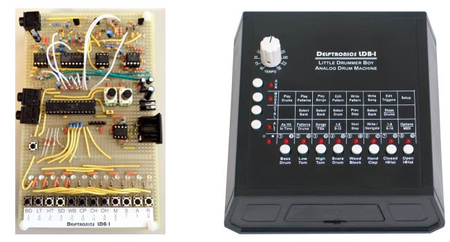
Drum Machine Prototype and Final Production Model
The circuits.
The rest of this article is a description of the LDB-1 circuits. The information presented below should provide you with everything you need to understand and even modify the LDB-1. If you have specific questions not answered by this article, please feel free to contact me. As you read the article, follow along with the LDB-1 Schematic .
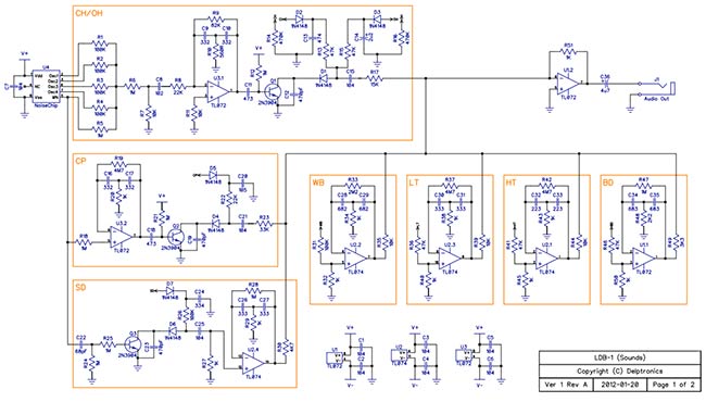
LBD1 Schematic - Download full schematic (PDF)
All those drum circuits.
The circuits in the LDB-1 are very similar to those used in classic analog drum machines, albeit greatly simplified. For example, compare the amount of circuitry for an individual LDB-1 drum with that of the TR-808. Page 9 of the TR-808 Service Manual shows the schematics for the drum sounds.
The circuit was too advanced for me at the time, but it stuck in my mind as something I would like to build eventually.
Each instrument in the TR-808 has two to three times more components than the corresponding circuit in the LDB-1. An important design goal of the LDB-1 was to make it as small and inexpensive as possible. To do that, the circuitry for each instrument was pared down to its core, and the component values were carefully tuned until it sounded perfect.
The LDB-1 uses bridged t-networks to produce decaying sine waves, just like the TR-808 and many other classic drum machines. The bridged t-network is actually a filter that is excited into self-oscillation by a pulse wave. In the LDB-1, the pulse is provided by the microcontroller. The circuits for the bass, toms, and woodblock are identical except for the resistor and capacitor values.
My first exposure to using bridged t-networks to produce drum sounds was in 1982 when I saw the Rhythm Pattern Generator schematic on page 143 of the Forrest Mims Engineer's Notebook. The circuit was too advanced for me at the time, but it stuck in my mind as something I would like to build eventually. It only took 30 years to get around to it.
Page 5 of the TR-808 Service Manual gives the schematic and formula for the bridged t-network.
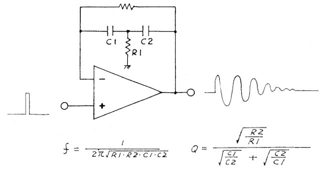
Representative Bridged T-Network (TR-808 Service Manual)
As you can see, the circuit consists of two resistors and two capacitors, all of which combine to determine the properties of the sound: the pitch, resonance, and decay. Changing any one of the values effects all three of the properties. Some rudimentary tuning of the pitch can be obtained by replacing R1 with a potentiometer. Given the relatively large resistors used by the LDB-1 for R2, at most a 5K pot is recommended. In the TR-808, there are quite a few additional components in the circuitry of each of the instruments that enable their pitch and/or decay to be tuned.
Snare Drum
A snare drum is really two sounds: the sound of the drum head being hit and the sound of the snare wires vibrating against the bottom resonant head of the drum.
The circuit for the snare drum contains the same bridged t-network used by the bass and toms, but instead of triggering it with a simple pulse, the snare drum is triggered with a burst of white noise. The white noise is first passively low pass filtered by C22 and R24. Then it is sent through a single transistor VCA (voltage controlled attenuator), a circuit referred to by the Roland engineers as a "Swing Type VCA." The VCA envelope is provided by a pulse from the microcontroller passing through a very simple RC circuit (R26 and C24). The same VCA circuit is used for the hi-hats.
The method of exciting the bridged t-network with white noise saves a lot of components when compared with the alternative method of separating the circuitry for the drum head and snare wires, triggering them both, then mixing their outputs.
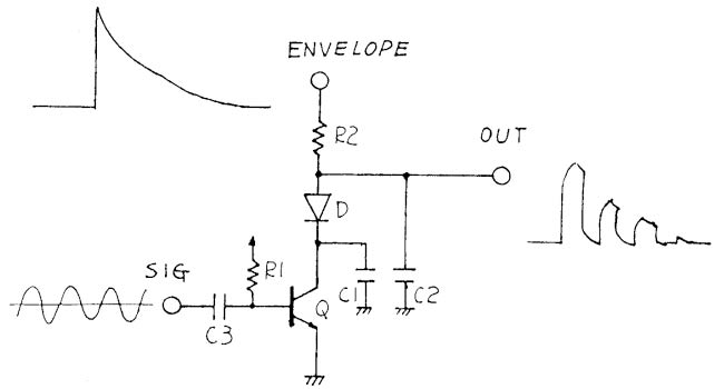
Representative Swing Type VCA (TR-808 Service Manual)
Cymbals
The simplest cymbal implementation uses filtered white noise. That is the method used in the earliest drum machines, but it is not very realistic. The method used by many later analog drum machines is to mix four or six tuned square waves to simulate the very complex harmonics of a cymbal. If the LDB-1 hi-hats sound a lot like the Boss DR-110, it is no coincidence. The LDB-1 uses four square waves at the same frequencies as the DR-110. A little white noise is added in as well, again, just like the DR-110. The result is a fairly realistic, and very nostalgic, sounding hi-hat.
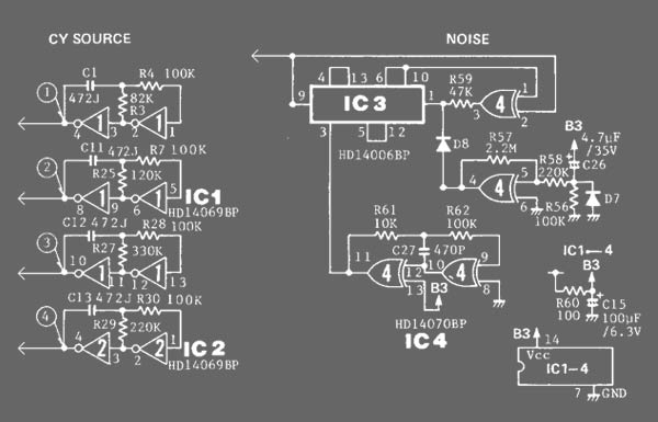
The "noise chip" in the LDB-1 schematic is a microcontroller programmed to output the digital white noise and four tuned square waves. The white noise is a 16-bit LFSR (linear feedback shift register) algorithm that produces a pseudo-random bit stream. The noise chip does exactly the same thing in a single 8-pin chip that the DR-110 did with twenty-seven discrete components, as you can see in the DR-110 schematic. (Click the picture below.)
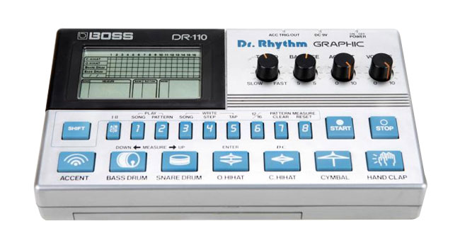
The Boss DR-110 Dr. Rhythm drum machine made by Roland and released in 1983. Click to learn more about the DR-110.
Boss DR-110 Cymbal and Noise Circuits
Boss, a division of Roland, introduced their Dr Beats series in 1983 with the DR-110. The new drum machine improved on previous models by adding rubber pads so you could "play" drums sounds in real time. Also added was an LCD (Liquid Crystal Display) screen.
The DR-110 had a whopping six voices: bass drum; snare drum; open hi-hat; closed hi-hat; hand clap; and cymbal. Yeah, one cymbal. But for the early 80's, it was a thing of beauty, acting not only as a metronome on crack, but also allowing for 128 measures to be chained together. That means you could program a song and play along. Pretty cool stuff.
The DR-110's bass and snare voices are generated by a damped tuned resonance oscillator. The cymbals and hi-hats, however, are created by VCA-shaping and band-pass filtering white noise and four non-harmonically related square wave oscillators.
R1 through R5 control the mix of the square waves and white noise. That mix is sent through a band pass filter (another bridged t-network), then through a single transistor VCA. The VCA envelope is provided by a pulse from the microcontroller passing through an RC circuit. The closed and open hi-hats use the same circuitry except for their envelopes. C13 determines the decay rate of the closed hi-hat, and C14 determines the decay of the open hi-hat.
Hand Clap
Hand clap sounds are a staple of drum machines, and absolutely had to be included in the LDB-1. The implementation is very simple. Band pass filtered white noise is passed through a VCA. Roland used two VCAs and a rather complex quadruple envelope waveform to generate the TR-808 hand clap (see page 6 of the service manual for a detailed description). I actually implemented that in the microcontroller software, but found that the sound was not very different from the simple method and did not warrant the extra code complexity.
Outputting the audio.
The individual instruments are mixed by op-amp U1.2. The seven resistors that feed into that op-amp are the mixing resistors and determine the relative volume of the instruments. You can raise or lower them to taste, or replace them with a 10k pot in series with a 1k resistor. A larger series resistor is recommended for the hand clap because it is proportionally much louder than the other instruments.
R51 controls the gain and, at 1k, provides line level output. If you need synth level output, R51 can be increased to 10k, or a 1k resistor in series with a 10k pot for variable gain. If you want to add a volume control to the output, a passive attenuator at the output is recommended over a 1k variable gain pot.
Some people have asked if it is possible to add separate audio outputs for each instrument. To do this, you would wire a resistor to the same point as the mixing resistor, and buffer the output through an op-amp. If you do not buffer the individual outputs, then the individual sound circuits will interact and distort one another.
If you are wondering why a circuit with eight op-amps uses one quad and two dual op-amp chips instead of two quad op-amp chips, it is because the cymbal and clap filters are (by design) noisy, and so are isolated in their own chip to avoid cross talk. The noisy chips also have a separate ground plane on the PCB.
The brains of the operation.
The microcontroller is what triggers the sound circuitry, handles button presses, lights LEDs, and communicates via MIDI and analog inputs and outputs. In some respects the requirements of the device determines the choice of microcontroller, and in other respects, the choice of microcontroller determines the capabilities of the device.
Microcontroller
The LDB-1 uses a Microchip PIC18F26K22 microcontroller. I chose a PIC microcontroller because I like working with PICs. That is a personal preference, because I have a good familiarity with the devices and tool chain. Other microcontroller families would have worked just as well.
I chose that particular microcontroller from the 700+ devices that Microchip offers for three reasons:
- I wanted it to be through-hole and DIY/kit friendly.
- I wanted a 28 pin part as opposed to a 40 pin part to keep the PCB small.
- I wanted as much EEPROM space as I could get because I wanted the LDB-1 to have non-volatile memory for the patterns, songs and config options and I did not want the added cost and board space of an external EEPROM chip.
The PIC18F26K22 has the most EEPROM memory of all of the 28 pin PICs, so it fit the bill. Actually, it is far more powerful than necessary. The LDB-1 code only uses half of the available RAM and less than half of the program memory. It is also much faster than necessary. It can run at up to 64 MHz. The LDB-1 runs it at 32 MHz, but even that is overkill.
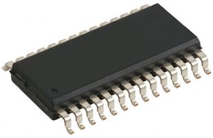
A PIC18F26K22 EEPROM microcontroller.
The amount of EEPROM memory, and the decision not to use an external EEPROM chip, indirectly determined the number of instruments. One byte is eight bits, so a single step in a pattern can be stored in a single byte as long as there are no more than 8 instruments. Using two bytes per step would halve the number of stored patterns.
The number of pins determines the number of connections to the rest of the circuit and to the outside world. So, having chosen the chip, I started counting pins and their functions. I went through many iterations of this to determine how many jacks, buttons and LEDs could be on the final device.
I settled on 12 buttons and 12 LEDs. The buttons are in a 3x4 matrix and use 12 pins. Each button has a diode so that multiple buttons can be pressed simultaneously without any ghosting or masking issues.
The LEDs are Charlieplexed, so only 4 pins drives all 12 LEDs. Only one LED is illuminated at a time, but they appear constant due to persistence of vision.
Connections
The outside world connections are audio output, trigger output, MIDI input, clock input and gate (start/stop) input. The MIDI jack can also be used as a DINsync input connection. DINsync was easy to implement because it uses pins that are not used by MIDI. The analog clock input and gate (start/stop) input jacks are wired right to the corresponding DINsync pins.
Trigger Output
The trigger output is a unique design that I am quite happy with. Most drum machines have trigger out on one or more instruments. The TR-808, for instance has a trigger output on the cowbell, clap, and accent. The LDB-1 has a single dedicated trigger output jack that is configurable to output trigger signals on any instruments and/or steps that the user chooses. The trigger output length is also configurable.
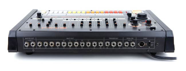
The I/O connections of a Roland TR-808.
Some people have asked if it is possible to add a separate trigger output for each instrument. The microcontroller triggers the instruments with a 4ms pulse. To send that pulse to a jack, you would connect a wire from the microcontroller pin that triggers each of the instruments to a buffer, and from there to an output jack. The separate trigger outputs must be buffered so that the circuitry plugged into the output jack does not interact with the LDB-1.
I'd like to thank...
Thanks to everyone at the Austin synth meets who gave their input and encouragement, to Guy Taylor for his advice and lending me his TR-606, and to Joseph Pailo for being the best beta tester ever.
Mickey Delp is an electronic musician and the chief inventor at Delptronics, purveyors of unique electronic musical instruments.