
-
By Mike Rivers

- Published Aug 26, 2013 in Gear Garage
Working with operating levels, impedance and common audio interfaces.
I’ve seen a lot of DAW demonstrations over the years. The demonstrator fires up the program showing a screen full of hot tracks, and then proceeds to demonstrate the program’s fantastic suite of mixing and processing tools. But did you ever wonder where those tracks came from? They had to be recorded somewhere, and it’s the rare demonstration that includes the tracking process. There’s a lot to understand before pressing the RECORD button, so when a factory demonstrator is playing for a large audience at a trade show or music store, it’s convenient to assume “everybody knows that.”
Well, not everybody knows that. Many artists have become proficient using prerecorded loops, samples, and virtual instrument plug-ins to create tunes with programs such as Garage Band. Now they want to incorporate vocals or real instruments in their songs and aren’t sure what they need or how to connect things. Here in Part 1, we’ll explain some fundamental concepts to help you make sense of all the specs, ads, reviews, and sketchy instruction manuals. Part 2 will cover audio interfaces, the part that gets the audio to and from the computer.
System Engineering 101 – Class is in Session
System Engineering is the study of interfaces, the science and art of making things work together. Sometimes this is simple, but when assembling a system comprised of multiple devices built by different manufacturers with an assortment of interface characteristics and connectors, It’s easy to get confused. Understanding concepts and jargon such as operating levels, impedance, balanced and unbalanced connections, and connector types will help you to select compatible pieces for your system and know what you can and can’t do when connecting diverse units.
Operating Levels - Microphone, Line, and Instrument
These are nominal, or ballpark voltages. For an input, it’s the voltage range over which that input operates best. Too much voltage causes overloading and distortion, too little voltage necessitates greater amplification further along the chain, often adding unwanted noise. For an output, this is the voltage range that you can reasonably expect to get out of the device, be it a microphone, a synthesizer, or reverb unit.
Microphones put out very little voltage (which is why they’re “micro”), ranging from a few millivolts to around 100 millivolts. We call voltages in this range “Mic Level.” Electronic keyboards, compressors or equalizers expect higher voltages at their inputs and produce higher voltages at their outputs, typically greater than 100 millivolts, up to about 6 volts. We call this “Line Level.” Instrument pickups are somewhere between microphones and line level devices. “Instrument Level” isn’t well defined, but the requirement for a high input impedance (which we’ll get to in a moment) makes the instrument input, whether a DI box or as part of a mic preamp a special design case.
Nominal Levels:
+4 dBu used to be called “Professional” level, but nowadays everybody wants (or expects) to be a professional. -10 dBV nominal operating level was established by TASCAM in the early days of “semi- pro” studio equipment. Your 25 year old yard sale stereo receiver may have a nominal operating level as much as 10 dB lower than this.
Operating levels are usually specified as nominal (middle-of-the-range) values using a decibel scale. The most common nominal “line” operating level today is +4 dBu which equals about 1.23 volts. The most common nominal line level for consumer audio equipment is -10 dBV, around 0.32 volts. Microphone levels are usually not described with a nominal value (it would be around –40 dBu), and instrument levels are in the -20 dBu ballpark.
Built-in computer sound cards are designed to work with consumer gear, so the line input your sound card (if it has one at all) probably has an operating level of around -10 dBV. Many aftermarket sound cards and stand-alone audio interfaces use the more professional +4 dBu operating level, with some offering a switch to accommodate either nominal operating level.
Nominal Levels vs. Headroom vs. Dynamic Range
Since the loudness of a musical performance can span a wide range, it’s convenient to have a target for the normal recording level. A nominal +4 dBu input can always accommodate a higher voltage than +4 dBu, but you don’t always know how much more. The difference between the nominal level (+4 dBu) and the level at which unpleasant distortion occurs (let’s say +22 dBu) is known as headroom. The level below which you can’t distinguish music from the system’s electronic noise is known as the noise floor. The difference between the noise floor (let’s say -87 dBu) and the maximum output level before distortion is the dynamic range.
Here’s a chart showing each of the common operating level ranges:
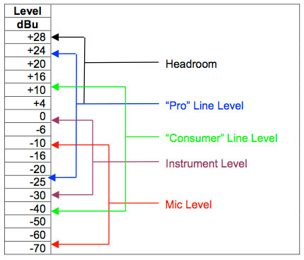
What’s important about all this is pretty simple: If the nominal levels of the devices you’re connecting aren’t the same, you’ll get unexpected results. Connect a nominal –10 dBV sound card output to the +4 dBu line input of a DJ mixer and you’ll need to set the mixer’s gain abnormally high to get a normal level showing on its meters. (You’ll probably jump on the manufacturer’s support forum asking “Is this normal?”) Connect the output of a professional PA mixer to a –10 dBV sound card input and you could get a distorted recording unless you lower the mixer’s master fader so that its meters are showing well below the normal operating level. There’s nothing wrong with using the controls you have available in order to match levels as long as you can do so, but your options might be limited if that mixer is simultaneously driving the PA system.
Due to their low output voltage, microphones always require a preamplifier. A mic preamp typically provides 20 to 60 dB of gain (amplification) to bring a mic signal up to Line Level. Once the signal is at line level, it usually stays at about that level throughout the audio chain. The preamp could be a stand-alone device or it could be built into the sound card or a mixer.
Impedance
Impedance is like electrical resistance and uses the same units, ohms. Sometimes it’s specified as a number, other times described simply as “high” or “low.” I’ve covered impedance in another article, so I won’t go into all the gory details here.
Nearly all professional microphones have a low impedance output, 50 to 300 ohms, and are designed to work as expected into an input impedance of 1,000 to 3,000 ohms. Modern line level devices typically have an output impedance of around 100 ohms and input impedance of 5,000 to 20,000 ohms. Instrument pickups, although they can approach line levels, are inherently high impedance devices and usually don’t sound very good unless connected to an input with an impedance of 100,000 ohms or greater. Loudspeakers are inherently low impedance, 4 to 16 ohms, though the input of a powered speaker (this is really an amplifier) is like any other line level device.
The important thing to understand about impedance is that we no longer match input and output impedance like we did in the early days. A modern compressor with a nominal output impedance of 100 ohms is designed to drive an input with an impedance of 5,000 ohms or greater. While common netlore tells us that when there’s a level mismatch, it’s a result of impedance mismatch, this is rarely the case.
So, does an impedance mismatch affect levels at all? You bet! Connect a device that’s specified as having a 100 ohm output impedance but expects a 5,000 ohm load to a device with an input impedance of 100 ohms and the output level will indeed drop, by 6 dB. That doesn’t sound like a big deal, but there’s a bigger problem. While the device can easily provide +20 dBu into its intended load, it doesn’t have sufficient power to develop that voltage into a 100 ohm load, with the result being that clipping will occur at a much lower level than normal. There’s nothing inherently wrong with this device (it was designed that way) as long as you understand how to use it properly.
Fortunately, with the exception of mic preamps, there aren’t too many modern audio devices with a low impedance input so you aren’t likely to encounter this problem. However, don’t connect the balanced XLR output of your compressor into the mic input of your mixer just because it, too, has an XLR connector. Use the line input instead even if you need to obtain an adapter or a special cable with different connectors on each end.
One innocent-seeming case you should be aware of is connecting low impedance outputs in parallel. If you want to combine a stereo output into mono, you might be tempted to use a Y cable to sum the left and right outputs. Remember that outputs are low impedance, so by connecting the two outputs together with the Y cable presents a low impedance load to each output. Even though each output by itself is clean up to its rated maximum output level, loading one with the low output impedance of the other can result in distortion when operating near maximum level.
Balanced/Unbalanced
This is one of the most misunderstood, and most worried-about interfacing concepts. It’s really pretty simple. You need two wires in order to have an electrical circuit. It’s also a good idea to use shielded cable for connecting audio devices. In a balanced connection, the two wires that carry the audio signal are both inside the shield. The shield doesn’t carry the signal (at least it’s not supposed to) but merely serves to protect the signal conductors from outside interference. In an unbalanced connection, there’s only one wire inside the shield; the shield doubles as the other signal conductor.
Two wires, more copper, more parts in the connectors, more expense . . . and more professional. People frequently make the distinction between professional and project studio gear simply by whether or not the input and output connections are balanced. There are advantages to using balanced connections, but with today’s higher operating levels and low source impedances, unbalanced connections work just fine most places where you find them. You need not be concerned that you’ll have poor audio quality if your gear has unbalanced connections.
Confusion about balanced connections stems from some older conventions. Unbalanced RCA phono jacks were the standard connectors on consumer “hi-fi” gear from the 1940s, and they’re still in common use. In the vacuum tube era, input and output impedances were higher than with modern solid state equipment, spawning the notion that all unbalanced connections are high impedance. Some of them are – instrument pickups are nearly always unbalanced and high impedance (active pickups are the exception here) and must be connected to a high impedance input such as an instrument amplifier or DI (Direct Injection or “direct”) box. The PA amplifier that in the janitor’s closet of your grandmother’s church used high impedance microphones, but nearly all the microphones that you’ll encounter today are low impedance and most have balanced outputs.
“Semi-pro” studio gear of the mid 1970s often used the RCA jacks and the -10 dBV operating level, both cost-saving measures. Nearly all of this gear, however, was solid state, so both input and output impedances were about as low as we know them today. You might have a problem getting a full level digital recording with a 1975-vintage TASCAM mixer feeding a modern +4 dBu sound card input, but this is because of their different operating levels, not an impedance mismatch, nor because the mixer is unbalanced and the sound card input is balanced.
Balanced connections do offer better immunity from electrical noise and, with properly designed equipment, there are fewer ground loop problems resulting from signal and hum being carried through the cable shield. If you have gear with balanced connections, spend the few bucks extra for “balanced” cables. It’s nearly always possible to interconnect balanced and unbalanced equipment, but there are several ways to handle that extra wire (or the lack of it).
You may encounter the description “impedance balanced” (usually in a review, it’s a term rarely used in marketing literature) which suggests that the device’s I/O isn’t really balanced. Don’t worry. The definition of a balanced connection is one in which each of the two signal wires from the source has the same impedance to ground. In the old days, a transformer served this purpose nicely, but transformers are expensive.
Designers found that they could achieve nearly the full benefit of a balanced connection by feeding the audio signal to one of the two output wires. The other wire carries no signal, but is connected to ground through a resistor with the same value as the output impedance of the circuit driving the signal wire. Presto! The definition of “balanced” is satisfied. When connected to a balanced (the correct term is “differential”) input, this arrangement provides almost as much noise immunity as a balanced output with both wires “hot”, at far lower cost than a transformer. Almost . . because the impedance match between the two leads isn’t perfect.
There are circuits that provide more accurate balancing with the use of more components than a single resistor (hence they cost more). So we have transformer balanced, electronic balanced, impedance balanced, and unbalanced.
Connectors – Square Pegs and Round Holes
OK, so there aren’t any square pegs (with the exception of D-subminiature connectors and some digital connectors) but not everything has the same type of connector. There are, however, several common connector types, and you shouldn’t be concerned about using a cable with different connectors on each end.
Studio and PA mics almost always have a balanced output on a male XLR connector. A balanced connection minimizes hum and noise pickup from what might be a fairly long cable. Also, an XLR connector locks in place so you won’t lose the signal (or the microphone) when the lead singer does rope tricks on stage. Beware that some chassis mounted female XLR connectors (and broken cable mounted connectors, too) do not lock. If you need the security, check for it.
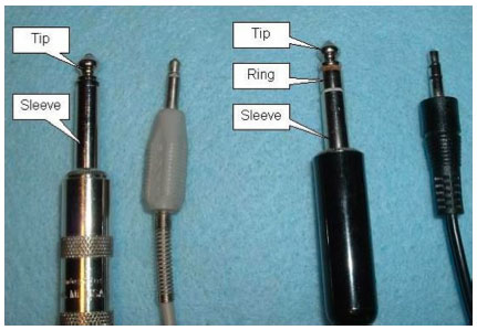
1/4” phone plugs and jacks, so named because of their diameter and that they were originally used on telephone switchboards, are probably the most common audio connector in today’s studios. They’re fairly inexpensive, robust, and they come in two flavors, suitable for unbalanced or balanced connections. They’re often called TRS and TS connectors named for their parts; tip, ring, and (on the two-conductor version), sleeve. A TRS connector is sometimes used to carry two channels such as a set of headphones or the type of stereo microphone often used with a portable recorder, hence they’re sometimes called “stereo” jacks or plugs even when used for balanced mono connections. A mixer’s “Insert” jacks are commonly the TRS configuration, with one conductor carrying an unbalanced output (send) and the other carrying an unbalanced input (return).
1/8” (mini) phone jacks and plugs are just like their 1⁄4” brethren only they’re smaller, less robust, and are commonly used on consumer audio devices, though they’re starting (much to my dismay) to find their way into some pro gear when size is critical, such as a handheld recorder. They’re all pretty flimsy (there’s no “premium” version), and often a mini jack is the first thing to fail on the device where it’s used. You’ll almost certainly find them on your computer’s built-in sound card as stereo inputs or outputs.
RCA phono connectors were common in the early days of the project studio because they’re cheaper than 1⁄4” jacks and pre-made cables were inexpensive and readily available. They’re unbalanced, often intermittent, and fortunately, aren’t common on modern studio gear other than perhaps as a mixer input or output to accommodate non-pro gear, or for S/PDIF digital connections.
Most people just getting your feet wet with computer recording start out using a built-in sound card, or you might choose to use it for those “it’s not so bad and it’s sure convenient” informal sessions, so make friends with the mini jacks. Nearly all output jacks on built-in sound cards are stereo though many now have six outputs for surround sound. You’ve probably already figured out the outputs after playing audio files for a while.
Inputs differ, however. Laptops typically have only one audio input jack, usually mono, and mic level only. Desktop computers sometimes have separate jacks for mic and line inputs. The line input will almost always be stereo and the mic input will usually be mono. You’ll need to do some experimenting (you could try reading the manual, but computer manuals aren’t what they used to be) to determine if your input jacks are mono or stereo, and at mic or line level. Today’s commercial concept of a computer audio input is a mic for telephone or video conferencing, not terribly conducive to music recording, but it’s a place to start.
One thing for certain is that your computer’s mic input jack won’t provide phantom power, so don’t buy an expensive condenser mic expecting to plug it into your computer with just an adapter. Some computers and portable recorders provide Plug-In Power, a low voltage microphone powering system used by some mics with 1/8” connectors. Check to see if yours has it, and learn how to turn it off unless you’re using a mic that requires it. While you can learn how recording works by plugging a mic into a sound card input, using a decent mic into an outboard mic preamp connected to the line input is one of the biggest improvements you can make in sound quality even if you’re not yet ready to give up that handy built-in sound card.
Sound Card Basics
Computer audio interfaces come in all sizes, shapes, and capabilities, the most basic one being the sound card built into your computer. It functions very much like a tape recorder, with the computer’s disk drive replacing the tape. The sound card converts the audio signal from a microphone or other sound source to a digital format which is stored as data in the computer’s memory or, more permanently, on disk. This data is read from disk into the sound card where it’s converted back to analog form which can drive loudspeakers or headphones.
The functional block diagram is pretty simple, and even though there’s a lot going on inside, today’s sound cards are built from just a couple of chips.
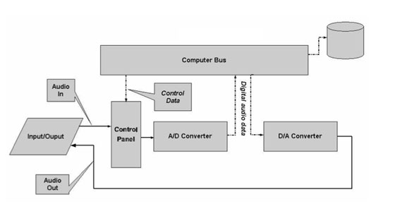
The Input section contains the microphone preamp which brings the small signal from the mic up to the level that the analog-to-digital converter can use. The sound card’s mic preamp is generally the weakest link in the recording chain. The analog-to-digital (A/D) converter changes the audio into digital format so that it can be stored on disk. Digital data from disk goes to the digital-to-analog (A/D) converter, where it comes out as audio. The accuracy of the converters used to be a weak spot, but today it’s hard to find a really bad sounding A/D or D/A converter. The Control Panel shown on the block diagram is actually a combination of hardware and software. The buttons and sliders that select the input and output sources and adjust the gain and volume can be popped up on the computer screen when you need them, with the computer sending commands to hardware on the sound card where the switching and level adjustments are actually performed, usually in the digital domain.
All of this can be improved upon. An aftermarket sound card will almost always have better converters than the ones selected by the computer manufacturer, though it may have only line inputs, requiring you to use an outboard preamp or mixer that (presumably) will offer better sound quality than a basic sound card’s mic input. But that can come later. You can start recording with what you have.
Assuming that you’re already set up for playback, all you need to figure out is how to connect your mic, and you’re ready to go. The simplest approach is to get a mic with a connector that matches the mic input connector on your sound card. Since this is most likely an 1/8” mono jack. It won’t be a great mic, but it’ll get sound into your computer. A better choice would be a dynamic mic from your PA system, but you’ll need to do some adapting to connect it to that mini jack. You can purchase a full length cable with a female XLR on one end and 1/8” plug on the other, but a better (and less costly) choice is to use a short adapter cable between the mini jack and a standard XLR mic cable. Since the mic input jack will almost certainly be unbalanced, be sure that the adapter has a TS (mono/unbalanced) mini plug rather than a TRS (stereo) plug.
Crank up your DAW program, select your sound card as the recording device (this will probably be the computer’s default setup), then open up the sound card’s on-screen control panel, push up the Mic fader, hit the Record button, and you’re recording.
There are many ways in which you can improve sound quality, ease of use, and work flow. In Part 2 we’ll talk about additions such as mixers and mic preamps, channel strips (mic preamp, EQ, compressor all in one box), all-in-one audio interfaces (mic preamp, line inputs and outputs, A/D and D/A converters, controls), digital I/O connections, alternate computer connections (Firewire, USB), headphones and monitoring, and studio operations.
Mike Rivers has written for the audio industry over the years, including a regular column for Recording Magazine, and two books. Mike has done his share of recording over the past 50 years including several years with a remote truck, as Gypsy Studio, primarily recording folk festivals for locally produced albums and radio broadcast. Mike is currently available for on-site consulting, technical writing, and regularly covers Music Industry topics on his blog Mike Rivers - Useful Audio Stuff.